mga
-
Numero contenuti
227 -
Iscritto
-
Ultima visita
Tipo di contenuto
Profili
Articoli
Introduzione alla stampa 3D
Database materiali
Forum
Calendario
Blogs
Gallery
Download
Store
Tutti i contenuti di mga
-
per una stampante delta, vorrei provare ad utilizzare una scheda MKS. Non va tutto bene però perché dopo homing, non riesco a spostare gli assi in x e y, mentre z funziona. La versione attuale dei parametri è in allegato. ho il sospetto che l'errore sia qui: # Travel limits after homing (units are in mm) >X_MIN_POS 0 >Y_MIN_POS 0 >Z_MIN_POS 0 >X_MAX_POS 0 >Y_MAX_POS 0 >Z_MAX_POS 256 cioè dopo homing forse non devo dire che si trova a Zmax e XY a zero?... però è così che cosa inibisce lo spostamento X e Y? Homing funziona e quindi se io sposto con la macchina spenta gli assi in qualunque posizione, poi li ripristina, quindi non c'è un problema negli assi e nemmeno negli endstop. Qualcuno ha un suggerimento? robin_nano_cfg.txt
-
MKS-Robin V.2.4 STM32 Scheda Madre e Controller Board con TFT 3 .2 POLLICI TOUCH
mga ha risposto a roberto76milano nella discussione Hardware e componenti
ciao, non ho risolto ancora il problema BL Touch sulla cartesiana, che ho messo una scheda nano su una delta. Per ora homing funziona correttamente. Terninato home posso spostare l'asse Z verso il basso, ma non posso muovere X o Y perché penso che siano impostati dei limiti non ammissibili. Ho provato a mettereil valore 0 ,0 Zmax quando eseguo home, ma non funziona lo stesso. Provo ad allegare i miei attuali parametri robin_nano_cfg.txt -
ciao. Chiedo aiuto per la configurazione di Robin Nano come da descrizione. Non era incluso il firmware e io non ho capito se questa funziona come Robin2, che ha un semplice file di testo da editare, oppure funziona con Marlin. Io spero sia conforme a Robin 2 - per non avere differenze operative. Ho scritto ai produttori, ma non mi hanno ancora risposto.
-
sto continuando a modificare il firmware nel tentativo di attivare il sensore touch. Viene riconosciuto, ma il livellamento automatico non funziona mai. Allego il file. Attenzione che non è nominato correttamente perché ne ho diverse varianti che rinomino solo al momento di caricarle sulla scheda. robin2_bltouch_2_cfg.txt
-
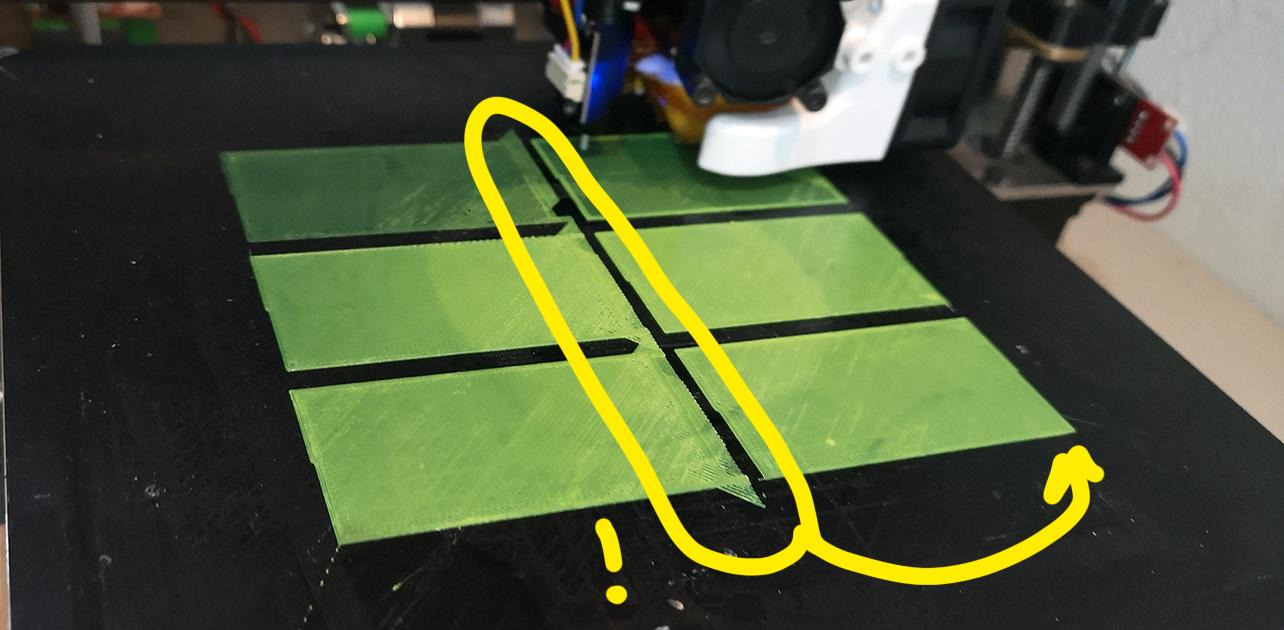
Cartesiana Reprap - scheda MKS Robin2 Ho creato con simplify 3d la ripetizione del medesimo oggetto. In fase di stampa sugli oggetti a sinistra del piano si sono creati degli artefatti che non capisco. Nello slicing non ci sono affatto. Non dipende dai duplicati, ma dalla posizione: mi si sono creati anche con un oggetto singolo. Ho allegato la foto che rappresenta l'anomalia. La parte sinistra cerchiata dovrebbe essere come a destra perché sono cloni. Da cosa può dipendere?

-
ho modificato in questo modo e ora mi fa il cliclo di accensione e spegnimento del sensore, tuttavia non va il livellamento e non mi riconosce i comandi di apertura e chiusura del sensore. #===================Language settings========================================== >cfg_language_adjust_type 1 #multi-language(enable:1, disable:0) >cfg_language_type 7 #languages setting,this configuration is valid when "cfg_multiple_language" is disabled. #(simplified Chinese:1; traditional Chinese:2; English:3; Russian:4; Spanish:5;French:6;Italian:7). #===================function settings======================================= >cfg_insert_det_module 0 #Assemble power outage module (1:mks 220det;0:mks pwc) >cfg_have_ups_device 0 #enable UPS?(yes:1; no:0) >cfg_print_over_auto_close 0 #auto-off when print finishes(1:yes£»0:no) >cfg_filament_det0_trigger_level 0 #the level signal of outage detection E0 module (1:high level;0:low level) >cfg_filament_det1_trigger_level 0 #the level signal of outage detection E1 module (1:high level;0:low level) >cfg_mask_det_function 0 #the function of power detecting and filament detecting(1:disable;0:enable) # the method of save the gcode data with power off(1:Capacitor storage; 0:File system save) >cfg_pwroff_save_mode 0 >cfg_filament_load_length 100 #the lenght to extrude filament (mm),Max:2000mm >cfg_filament_load_speed 800 #the speed to extrude filament(mm/min) >cfg_filament_load_limit_temperature 200 #It is the minimum temperature to extrude filament . >cfg_filament_unload_length 100 #It is the minimum temperature to extrude filament . >cfg_filament_unload_speed 800 #the speed to retract filament(mm/min) >cfg_filament_unload_limit_temperature 200 #It is the minimum temperature to retract filament . #=========================== Leveling button settings ============================= >cfg_leveling_mode 1 #1:auto-leveling; 0:manual leveling #=========================== manual leveling ================================== >cfg_point_number 5 #the point number of manual leveling(3,4,5 point available) #the 5 point location of manual leveling >cfg_point1:10,10 >cfg_point2:190,10 >cfg_point3:190,190 >cfg_point4:10,190 >cfg_point5:100,100 #========================== auto leveling =================================== >cfg_auto_leveling_cmd:G28;G29; #==================Display Effect(refer to MKS TFT datasheet)=================================== #user-defined function1 >setmenu_func1_display 1 #1:display this button£¬0:no #each command must be separated by semicolon ";" >setmenu_func1:M84; >moreitem_pic_cnt 0 #the number of "more" button #edit command for 1~7 "More" button #each command must be separated by semicolon ";" #each icon command must be less than 200 bytes >moreitem_button1_cmd:G28 X0;G28 Y0;G28 Z0; >moreitem_button2_cmd:G28 X0;G28 Y0;G28 Z0; >moreitem_button3_cmd:G28 X0;G28 Y0;G28 Z0; >moreitem_button4_cmd:G28 X0;G28 Y0;G28 Z0; >moreitem_button5_cmd:G28 X0;G28 Y0;G28 Z0; >moreitem_button6_cmd:G28 X0;G28 Y0;G28 Z0; >moreitem_button7_cmd:G28 X0;G28 Y0;G28 Z0; #the number of "more" button to dispaly on printing interface >morefunc_cnt 0 #button1~button6 function >morefunc1_cmd:G28; >morefunc2_cmd:G28; >morefunc3_cmd:G28; >morefunc4_cmd:G28; >morefunc5_cmd:G28; >morefunc6_cmd:G28; >morefunc7_cmd:G28; #------------------------------------------------------------- ######## Display Customization ########## >cfg_background_color 0x000000 #the color of screen background >cfg_title_color 0xFFFFFF #the color of title text >cfg_state_bkcolor 0x000000 #the color of temperature,fan,(etc)background >cfg_state_textcolor 0xFFFFFF #the color of temprature,fan,(etc) text >cfg_filename_bkcolor 0x000000 #the color of file button >cfg_filename_textcolor 0xFFFFFF #the color of file text >cfg_btn_bkcolor 0x000000 #Universal button background color >cfg_btn_textcolor 0xFFFFFF #Universal button text color >cfg_state_btn_bkcolor 0x000000 #Status button background color >cfg_state_btn_textcolor 0xFFFFFF #Status button text color >cfg_back_btn_bkcolor 0x000000 #Button of Return background color >cfg_back_btn_textcolor 0xFFFFFF #Button of Return text color >cfg_sel_btn_bkcolor 0x000000 #Selected button background color >cfg_sel_btn_textcolor 0xFFFFFF #Selected button text color >cfg_dialog_btn_bkcolor 0xff0000 #Dialog button background color >cfg_dialog_btn_textcolor 0xFFFFFF #Dialog button text color >cfg_btn_text_offset 23 #position of button font offset bottom(unit:pixel) >cfg_screen_display_mode 1 #the style of display on the screen home(0:classic,1:simple) #============================= Basic Settings ========================= >MACHINETPYE 0 # 0:Cartesian; 1:DELTA ; 2:COREXY #LCD_LANGUAGE 0 # 0:English; 1:Chinese >HAS_TEMP_BED 1 # whether enable the heated bed (disable: 0, enable: 1) >EXTRUDERS 1 # This defines the number of extruders >Z2_STEPPER_DRIVERS 1 #enable z2; 0:disable; 1:enable z_dual; >Z2_ENDSTOPS 1 #enable z2_endstop; 0:disable z_dual_endstop; 1:enable z_dual_endstop; >Z2_USE_ENDSTOP 1 #use X_MIN or X_MAX; 0:unused;1:X_MAX; 2:X_MIN # Travel limits after homing (units are in mm) >X_MIN_POS -20 >Y_MIN_POS -20 >Z_MIN_POS 0 >X_MAX_POS 200 >Y_MAX_POS 200 >Z_MAX_POS 190 # position of hotend for filament change and pause print >FILAMENT_CHANGE_X_POS 5 # X position of hotend for filament change and pause print >FILAMENT_CHANGE_Y_POS 5 # Y position of hotend for filament change and pause print >FILAMENT_CHANGE_Z_ADD 5 # Z addition of hotend (lift) for filament change and pause print #Offset of the second extruders. >HOTEND_OFFSET_X 20.00 #(in mm) offset of the second hotend on the X axis ,Offsets for the first hotend must be 0.0. >HOTEND_OFFSET_Y 5.00 #(in mm) offset of the second hotend on the Y axis ,Offsets for the first hotend must be 0.0. #============================== Stepper Motor Settings ============================ #Invert the stepper direction. >INVERT_X_DIR 0 >INVERT_Y_DIR 0 >INVERT_Z_DIR 0 >INVERT_E0_DIR 1 >INVERT_E1_DIR 0 #Movement setting >DEFAULT_X_STEPS_PER_UNIT 160.00 #Default Axis-X Steps Per Unit (steps/mm) >DEFAULT_Y_STEPS_PER_UNIT 162.70 #Default Axis-Y Steps Per Unit (steps/mm) >DEFAULT_Z_STEPS_PER_UNIT 797.00 #Default Axis-Z Steps Per Unit (steps/mm) >DEFAULT_E0_STEPS_PER_UNIT 319.46 #Default Axis-E0 Steps Per Unit (steps/mm) >DEFAULT_E1_STEPS_PER_UNIT 797.00 #Default Axis-E1 Steps Per Unit (steps/mm) >DEFAULT_X_MAX_FEEDRATE 200 #Default Axis-X Max Feed Rate (mm/s) >DEFAULT_Y_MAX_FEEDRATE 200 #Default Axis-Y Max Feed Rate (mm/s) >DEFAULT_Z_MAX_FEEDRATE 4 #Default Axis-Z Max Feed Rate (mm/s) >DEFAULT_E0_MAX_FEEDRATE 70 #Default Axis-E0 Max Feed Rate (mm/s) >DEFAULT_E1_MAX_FEEDRATE 4 #Default Axis-E1 Max Feed Rate (mm/s) >DEFAULT_X_MAX_ACCELERATION 1000 #Default Axis-X Max Acceleration (change/s) change = mm/s >DEFAULT_Y_MAX_ACCELERATION 1000 #Default Axis-Y Max Acceleration (change/s) change = mm/s >DEFAULT_Z_MAX_ACCELERATION 100 #Default Axis-Z Max Acceleration (change/s) change = mm/s >DEFAULT_E0_MAX_ACCELERATION 1000 #Default Axis-E0 Max Acceleration (change/s) change = mm/s >DEFAULT_E1_MAX_ACCELERATION 100 #Default Axis-E1 Max Acceleration (change/s) change = mm/s >DEFAULT_ACCELERATION 1000 #X, Y, Z and E acceleration for printing moves >DEFAULT_RETRACT_ACCELERATION 1000 #X, Y, Z and E acceleration for retracts >DEFAULT_TRAVEL_ACCELERATION 1000 #X, Y, Z acceleration for travel (non printing) moves >DEFAULT_MINIMUMFEEDRATE 0.0 #minimum feedrate >DEFAULT_MINSEGMENTTIME 20000 #minimum time in microseconds that a movement needs to take if the buffer is emptied. >DEFAULT_MINTRAVELFEEDRATE 0.0 # >DEFAULT_XJERK 24.0 #Default Axis-X Jerk (mm/s) >DEFAULT_YJERK 24.0 #Default Axis-Y Jerk (mm/s) >DEFAULT_ZJERK 0.5 #Default Axis-Z Jerk (mm/s) >DEFAULT_EJERK 5.0 #Default Axis-E Jerk (mm/s) #For Inverting Stepper Enable Pins (0:Low,1:High) >X_ENABLE_ON 0 >Y_ENABLE_ON 0 >Z_ENABLE_ON 0 >E_ENABLE_ON 0 #============================= Thermal Settings ============================ >TEMP_SENSOR_0 1 #1: 100k thermistor£»-3 : thermocouple with MAX31855 >EXTRUDE_MINTEMP 170 >HEATER_0_MINTEMP 5 >HEATER_0_MAXTEMP 275 >HEATER_1_MINTEMP 5 >HEATER_1_MAXTEMP 275 >BED_MAXTEMP 120 #======================== Thermal Runaway Protection ======================= >THERMAL_PROTECTION_PERIOD 40 #Seconds >THERMAL_PROTECTION_HYSTERESIS 4 #Degrees Celsius >WATCH_TEMP_PERIOD 40 #Seconds >WATCH_TEMP_INCREASE 2 #Degrees Celsius >THERMAL_PROTECTION_BED_PERIOD 40 #Seconds >THERMAL_PROTECTION_BED_HYSTERESIS 4 #Degrees Celsius >WATCH_BED_TEMP_PERIOD 60 #Seconds >WATCH_BED_TEMP_INCREASE 2 #Degrees Celsius # Type of heat manager for extruder. >PIDTEMPE 1 # 1:PID ; 0:bang-bang >DEFAULT_Kp 22.2 # --default >DEFAULT_Ki 1.08 # --default >DEFAULT_Kd 114 # --default #Type of heat manager for this heatedBed. >PIDTEMPBED 1 # 1:PID ; 0:bang-bang >DEFAULT_bedKp 10.00 # --default >DEFAULT_bedKi 0.023 # --default >DEFAULT_bedKd 305.4 # --default #============================== Endstop Settings =========================== >MIN_SOFTWARE_ENDSTOPS 1 # 0:axes can move below MIN_POS; 1:axes won't move below MIN_POS. >MAX_SOFTWARE_ENDSTOPS 1 # 0:axes can move below MAX_POS; 1:axes won't move below MIN_POS. # Mechanical endstop with COM to ground and NC to Signal uses "false" here (most common setup). >X_MIN_ENDSTOP_INVERTING 1 # set to true to invert the logic of the endstop. >Y_MIN_ENDSTOP_INVERTING 1 # set to true to invert the logic of the endstop. >Z_MIN_ENDSTOP_INVERTING 1 # set to true to invert the logic of the endstop. >X_MAX_ENDSTOP_INVERTING 1 # set to true to invert the logic of the endstop. >Y_MAX_ENDSTOP_INVERTING 0 # set to true to invert the logic of the endstop. >Z_MAX_ENDSTOP_INVERTING 1 # set to true to invert the logic of the endstop. >Z_MIN_PROBE_ENDSTOP_INVERTING 1 # set to true to invert the logic of the probe. >FIL_RUNOUT_INVERTING 0 # set to true to invert the logic of the Filament Runout Sensor. # Specify here all the endstop connectors that are connected to any endstop or probe. >USE_XMIN_PLUG 1 # 1:used; 0:noused >USE_YMIN_PLUG 1 # 1:used; 0:noused >USE_ZMIN_PLUG 1 # 1:used; 0:noused >USE_XMAX_PLUG 1 # 1:used; 0:noused >USE_YMAX_PLUG 0 # 1:used; 0:noused >USE_ZMAX_PLUG 1 # 1:used; 0:noused #============================== Home Settings ============================== >X_HOME_DIR -1 # Direction of endstops when homing; 1=MAX, -1=MIN :[-1,1] >Y_HOME_DIR -1 # Direction of endstops when homing; 1=MAX, -1=MIN :[-1,1] >Z_HOME_DIR -1 # Direction of endstops when homing; 1=MAX, -1=MIN :[-1,1] >HOMING_FEEDRATE_XY 2400 # Homing X Y speeds (mm/m) >HOMING_FEEDRATE_Z 600 # Homing Z speeds (mm/m) >HOME_Y_BEFORE_X 0 # When G28 is called,0: X home before Y; 1: Y home before X #============================= Z Probe Options ============================= >BLTOUCH 1 # 0:disable BLTOUCH; 1:enable BLTOUCH #Select for a probe connected to Z-Min or Z-Max. >Z_MIN_PROBE_PIN_MODE 2 # 0 : NULL; 1: ZMIN; 2: ZMAX >Z_PROBE_OFFSET_FROM_EXTRUDER 1.75 # Z offset: -below +above [the nozzle] >X_PROBE_OFFSET_FROM_EXTRUDER -29 # X offset: -left +right [of the nozzle] >Y_PROBE_OFFSET_FROM_EXTRUDER -1.5 # Y offset: -front +behind [the nozzle] >XY_PROBE_SPEED 4000 # X and Y axis travel speed (mm/m) between probes >Z_PROBE_SPEED_FAST 600 # Speed for the first approach when double-probing (with PROBE_DOUBLE_TOUCH) >Z_PROBE_SPEED_SLOW 300 # Speed for the "accurate" probe of each point #=============================== Bed Leveling ============================== >BED_LEVELING_METHOD 3 # 0:NULL_BED_LEVELING; 3:AUTO_BED_LEVELING_BILINEAR; 5:MESH_BED_LEVELING >GRID_MAX_POINTS_X 3 # the number of grid points per dimension. <= 15 >GRID_MAX_POINTS_Y 3 # the number of grid points per dimension. <= 15 >Z_CLEARANCE_DEPLOY_PROBE 20 # Z Clearance for Deploy/Stow > 0 >Z_CLEARANCE_BETWEEN_PROBES 20 # Z Clearance between probe points > 0 # Set the boundaries for probing (where the probe can reach). >LEFT_PROBE_BED_POSITION 30 >RIGHT_PROBE_BED_POSITION 180 >FRONT_PROBE_BED_POSITION 30 >BACK_PROBE_BED_POSITION 180 >MESH_INSET 20 # Mesh inset margin on print area for MESH_BED_LEVELING #============================== Delta Settings ============================= >DELTA_SEGMENTS_PER_SECOND 40 #--default >DELTA_DIAGONAL_ROD 346.75 #Center-to-center distance of the holes in the diagonal push rods. >DELTA_SMOOTH_ROD_OFFSET 211.5 #Horizontal offset from middle of printer to smooth rod center. >DELTA_EFFECTOR_OFFSET 28 #Horizontal offset of the universal joints on the end effector. >DELTA_CARRIAGE_OFFSET 14.5 #Horizontal offset of the universal joints on the carriages. >DELTA_RADIUS 169 #Horizontal distance bridged by diagonal push rods when effector is centered. >DELTA_HEIGHT 302 #height from z=0.00 to home position >DELTA_PRINTABLE_RADIUS 125 #Print surface diameter/2 minus unreachable space (avoid collisions with vertical towers). >DELTA_CALIBRATION_RADIUS 100 #set the radius for the calibration probe points - max 0.8 * DELTA_PRINTABLE_RADIUS #============================== Wifi Settings ============================= >CFG_WIFI_MODE 1 #wifi mode(0:sta;1:ap) >CFG_WIFI_AP_NAME TP-LINK_C944 #wifi name >CFG_WIFI_KEY_CODE makerbase #wifi password >CFG_CLOUD_ENABLE 1 #cloud service enable(0:disable; 1:enable) >CFG_WIFI_CLOUD_HOST www.baizhongyun.cn #cloud server url >CFG_CLOUD_PORT 10086 #cloud server port #end.
-
Mi è arrivato il sensore touch. Siccome ho suddiviso gli endstop z occupando un endstopx, ora per il segnale bltouch devo utilizzare la connessione zmax. Premetto, che se anche si accende il sensore, non funziona e non effettua il classico ciclo iniziale dove si attiva la sonda per alcuni cicli. Qui i parametri adottati sotto riporto i parametri che ho inserito. Qualcuno mi può aiutare? # Specify here all the endstop connectors that are connected to any endstop or probe. >USE_XMIN_PLUG 1 # 1:used; 0:noused >USE_YMIN_PLUG 1 # 1:used; 0:noused >USE_ZMIN_PLUG 1 # 1:used; 0:noused >USE_XMAX_PLUG 1 # 1:used; 0:noused >USE_YMAX_PLUG 0 # 1:used; 0:noused >USE_ZMAX_PLUG 1 # 1:used; 0:noused #============================== Home Settings ============================== >X_HOME_DIR -1 # Direction of endstops when homing; 1=MAX, -1=MIN :[-1,1] >Y_HOME_DIR -1 # Direction of endstops when homing; 1=MAX, -1=MIN :[-1,1] >Z_HOME_DIR -1 # Direction of endstops when homing; 1=MAX, -1=MIN :[-1,1] >HOMING_FEEDRATE_XY 2400 # Homing X Y speeds (mm/m) >HOMING_FEEDRATE_Z 600 # Homing Z speeds (mm/m) >HOME_Y_BEFORE_X 0 # When G28 is called,0: X home before Y; 1: Y home before X #============================= Z Probe Options ============================= >BLTOUCH 1 # 0:disable BLTOUCH; 1:enable BLTOUCH #Select for a probe connected to Z-Min or Z-Max. >Z_MIN_PROBE_PIN_MODE 2 # 0 : NULL; 1: ZMIN; 2: ZMAX >Z_PROBE_OFFSET_FROM_EXTRUDER 1.75 # Z offset: -below +above [the nozzle] >X_PROBE_OFFSET_FROM_EXTRUDER -29 # X offset: -left +right [of the nozzle] >Y_PROBE_OFFSET_FROM_EXTRUDER -1.5 # Y offset: -front +behind [the nozzle] >XY_PROBE_SPEED 4000 # X and Y axis travel speed (mm/m) between probes >Z_PROBE_SPEED_FAST 600 # Speed for the first approach when double-probing (with PROBE_DOUBLE_TOUCH) >Z_PROBE_SPEED_SLOW 300 # Speed for the "accurate" probe of each point #=============================== Bed Leveling ============================== >BED_LEVELING_METHOD 5 # 0:NULL_BED_LEVELING; 3:AUTO_BED_LEVELING_BILINEAR; 5:MESH_BED_LEVELING >GRID_MAX_POINTS_X 3 # the number of grid points per dimension. <= 15 >GRID_MAX_POINTS_Y 3 # the number of grid points per dimension. <= 15 >Z_CLEARANCE_DEPLOY_PROBE 20 # Z Clearance for Deploy/Stow > 0 >Z_CLEARANCE_BETWEEN_PROBES 20 # Z Clearance between probe points > 0 # Set the boundaries for probing (where the probe can reach). >LEFT_PROBE_BED_POSITION 20 >RIGHT_PROBE_BED_POSITION 180 >FRONT_PROBE_BED_POSITION 20 >BACK_PROBE_BED_POSITION 180 >MESH_INSET 20 # Mesh inset margin on print area for MESH_BED_LEVELING
-
Anycubic Chiron centro
mga ha risposto a mga nella discussione Problemi generici o di qualità di stampa
ti ha risposto bene marcott... mi raccomando ripristina i cavi!!! La ventola di livello la imposti tu e la puoi anche attivare con Simplify3d o con altri programmi collegati direttamente e puoi modificare la velocità di rotazione. La ventola sul corpo invece si attiva quando l'ugello raggiunge una certa temperatura. Da me non è sempre attiva - come avviene con altre stampanti. -
Anycubic Chiron centro
mga ha risposto a mga nella discussione Problemi generici o di qualità di stampa
sì ricordo anche io che la prima taratura ha un offset notevole, ma bisogna ridurlo. Il mio se non ricordo male era esagerato. Siccome non è l'unica stampante che ho e ognuna ha un suo mondo, non mi ricordo come ho fatto, ma mi pare di aver fatto un intervento nei parametri offset utilizzando però la gestione generale dell'offset su tutti i punti per poi andare a calibrarla punto per punto e per questo volevo una griglia perfetta in corrispondenza dell'estrusore! -
Anycubic Chiron centro
mga ha risposto a mga nella discussione Problemi generici o di qualità di stampa
non so a quale livello di perfezione tu faccia riferimento... mi pare piano e senza visibili avallamenti. Ad ogni modo ho livellato il piano intervenendo nei vari punti in modo differente a seconda dell'adesione che riscontravo quindi... se parliamo di perfezione... non è piano al 100%. -
Anycubic Chiron centro
mga ha risposto a mga nella discussione Problemi generici o di qualità di stampa
no, non ho risolto il problema specifico, ma loro mi hanno scritto di non considerare questo, quanto piuttosto il livellamento del piano. Non importa che l'ugello sia esattamente nell'incrocio, ma che il piano sia livellato. Io invece non lo disegno nemmeno un incrocio se poi non ho intenzione di utilizzarlo come riferimento. L'unica soluzione sarebbe lo spostamento fisico dell'origine della prima coordinata... cosa che sicuramente non rischio di fare. Si sarebbe potuto via firmware, ma non viene fornito un firmware modificabile e quindi... non ci sono soluzioni. -
"script per la variazione di layer" ma questo lo posso lasciare sempre o lo devo compilare solo quando ho un processo diviso? Io pensavo infatti che se avessi inserito uno script in questa posizione ad ogni livello me lo avrebbe eseguito... non pensavo proprio a questa situazione
-
simplify 3d - Anycubic Chiron Lo chiedo per Simplify 3d, ma la domanda potrebbe essere generica. Vorrei creare un processo diviso con cambio di colore dopo un livello di 4mm. Raggiunto il livello la stampante dovrebbe essere messa in pausa e dovrei effettuare il cambio di filamento per poi riprendere con il nuovo colore. 1) Quale gcode mi consigliate utilizzare per queste operazioni? 2) Mi pare che Simplify 3d con il processo diviso ignori i gcode finale e iniziale quando lancio la stampa selezionandoli entrambi (per esempio quando cambio solo infill). Ma in questo caso a me serve una pausa di processo per il cambio... dove va inserito il gcode?
-
che colla hai usato? ma tu hai stampato anche il piano o solo le scritte? io stavo pensando di stampare il rettangolo di un colore e le scritte con un altro di modo che aderiscano sul piano e poi... forse come dici tu su un supporto... ma cosa dici se invece prendessi una superficie pvc colorata e stampassi direttamente su quella con uno z offset?
-
Volevo stampare una targa esterna da mettere su un muretto. Pensavo di utilizzare più colori, ma ho PLA. Forse non è giusto... il PLA al caldo potrebbe deformarsi. E poi le targhe sono piani rettangolari su cui sovrapporre in rilievo dei testi... ma mi pare assurdo stampare un piano rettangolare... forse meglio stampare le scrite e poi incollarle? Ma con cosa? Forse meglio non considerare una cosa del genere perché poco logica?
-
comunque sono in attesa di sensore touch per livellamento automatico e così elimino il problema alla radice. Giustissima la questione del mantenere in squadra l'asse X 😮... che ho appena verificato. Mi pare che funzioni tutto e gli endstop siano indipendenti ora.
-
in relazione a quando domandato sopra ... forse è questa parte? Dato che endstop z2 è xmax forse dovrei indicare come Xmax 200 anziché 210 ...? Il piano è 21x21x20 # Travel limits after homing (units are in mm) >X_MIN_POS -20 >Y_MIN_POS -20 >Z_MIN_POS 0 >X_MAX_POS 210 >Y_MAX_POS 210 >Z_MAX_POS 200 tanto per conoscenza... Mi sono accorto che avevo attivato per errore anche Zmax che non era presente e poi ho pensato di modifcare xyz max in 200 e mi pare che ora funzioni. questi sotto sono i parametri nuovi #===================Language settings========================================== >cfg_language_adjust_type 1 #multi-language(enable:1, disable:0) >cfg_language_type 7 #languages setting,this configuration is valid when "cfg_multiple_language" is disabled. #(simplified Chinese:1; traditional Chinese:2; English:3; Russian:4; Spanish:5;French:6;Italian:7). #===================function settings======================================= >cfg_insert_det_module 0 #Assemble power outage module (1:mks 220det;0:mks pwc) >cfg_have_ups_device 0 #enable UPS?(yes:1; no:0) >cfg_print_over_auto_close 0 #auto-off when print finishes(1:yes£»0:no) >cfg_filament_det0_trigger_level 0 #the level signal of outage detection E0 module (1:high level;0:low level) >cfg_filament_det1_trigger_level 0 #the level signal of outage detection E1 module (1:high level;0:low level) >cfg_mask_det_function 0 #the function of power detecting and filament detecting(1:disable;0:enable) # the method of save the gcode data with power off(1:Capacitor storage; 0:File system save) >cfg_pwroff_save_mode 0 >cfg_filament_load_length 100 #the lenght to extrude filament (mm),Max:2000mm >cfg_filament_load_speed 800 #the speed to extrude filament(mm/min) >cfg_filament_load_limit_temperature 200 #It is the minimum temperature to extrude filament . >cfg_filament_unload_length 100 #It is the minimum temperature to extrude filament . >cfg_filament_unload_speed 800 #the speed to retract filament(mm/min) >cfg_filament_unload_limit_temperature 200 #It is the minimum temperature to retract filament . #=========================== Leveling button settings ============================= >cfg_leveling_mode 0 #1:auto-leveling; 0:manual leveling #=========================== manual leveling ================================== >cfg_point_number 5 #the point number of manual leveling(3,4,5 point available) #the 5 point location of manual leveling >cfg_point1:10,10 >cfg_point2:190,10 >cfg_point3:190,190 >cfg_point4:10,190 >cfg_point5:100,100 #========================== auto leveling =================================== >cfg_auto_leveling_cmd:G28;G29; #==================Display Effect(refer to MKS TFT datasheet)=================================== #user-defined function1 >setmenu_func1_display 1 #1:display this button£¬0:no #each command must be separated by semicolon ";" >setmenu_func1:M84; >moreitem_pic_cnt 0 #the number of "more" button #edit command for 1~7 "More" button #each command must be separated by semicolon ";" #each icon command must be less than 200 bytes >moreitem_button1_cmd:G28 X0;G28 Y0;G28 Z0; >moreitem_button2_cmd:G28 X0;G28 Y0;G28 Z0; >moreitem_button3_cmd:G28 X0;G28 Y0;G28 Z0; >moreitem_button4_cmd:G28 X0;G28 Y0;G28 Z0; >moreitem_button5_cmd:G28 X0;G28 Y0;G28 Z0; >moreitem_button6_cmd:G28 X0;G28 Y0;G28 Z0; >moreitem_button7_cmd:G28 X0;G28 Y0;G28 Z0; #the number of "more" button to dispaly on printing interface >morefunc_cnt 0 #button1~button6 function >morefunc1_cmd:G28; >morefunc2_cmd:G28; >morefunc3_cmd:G28; >morefunc4_cmd:G28; >morefunc5_cmd:G28; >morefunc6_cmd:G28; >morefunc7_cmd:G28; #------------------------------------------------------------- ######## Display Customization ########## >cfg_background_color 0x000000 #the color of screen background >cfg_title_color 0xFFFFFF #the color of title text >cfg_state_bkcolor 0x000000 #the color of temperature,fan,(etc)background >cfg_state_textcolor 0xFFFFFF #the color of temprature,fan,(etc) text >cfg_filename_bkcolor 0x000000 #the color of file button >cfg_filename_textcolor 0xFFFFFF #the color of file text >cfg_btn_bkcolor 0x000000 #Universal button background color >cfg_btn_textcolor 0xFFFFFF #Universal button text color >cfg_state_btn_bkcolor 0x000000 #Status button background color >cfg_state_btn_textcolor 0xFFFFFF #Status button text color >cfg_back_btn_bkcolor 0x000000 #Button of Return background color >cfg_back_btn_textcolor 0xFFFFFF #Button of Return text color >cfg_sel_btn_bkcolor 0x000000 #Selected button background color >cfg_sel_btn_textcolor 0xFFFFFF #Selected button text color >cfg_dialog_btn_bkcolor 0xff0000 #Dialog button background color >cfg_dialog_btn_textcolor 0xFFFFFF #Dialog button text color >cfg_btn_text_offset 23 #position of button font offset bottom(unit:pixel) >cfg_screen_display_mode 1 #the style of display on the screen home(0:classic,1:simple) #============================= Basic Settings ========================= >MACHINETPYE 0 # 0:Cartesian; 1:DELTA ; 2:COREXY #LCD_LANGUAGE 0 # 0:English; 1:Chinese >HAS_TEMP_BED 1 # whether enable the heated bed (disable: 0, enable: 1) >EXTRUDERS 1 # This defines the number of extruders >Z2_STEPPER_DRIVERS 1 #enable z2; 0:disable; 1:enable z_dual; >Z2_ENDSTOPS 1 #enable z2_endstop; 0:disable z_dual_endstop; 1:enable z_dual_endstop; >Z2_USE_ENDSTOP 1 #use X_MIN or X_MAX; 0:unused;1:X_MAX; 2:X_MIN # Travel limits after homing (units are in mm) >X_MIN_POS -20 >Y_MIN_POS -20 >Z_MIN_POS 0 >X_MAX_POS 200 >Y_MAX_POS 200 >Z_MAX_POS 200 # position of hotend for filament change and pause print >FILAMENT_CHANGE_X_POS 5 # X position of hotend for filament change and pause print >FILAMENT_CHANGE_Y_POS 5 # Y position of hotend for filament change and pause print >FILAMENT_CHANGE_Z_ADD 5 # Z addition of hotend (lift) for filament change and pause print #Offset of the second extruders. >HOTEND_OFFSET_X 20.00 #(in mm) offset of the second hotend on the X axis ,Offsets for the first hotend must be 0.0. >HOTEND_OFFSET_Y 5.00 #(in mm) offset of the second hotend on the Y axis ,Offsets for the first hotend must be 0.0. #============================== Stepper Motor Settings ============================ #Invert the stepper direction. >INVERT_X_DIR 0 >INVERT_Y_DIR 0 >INVERT_Z_DIR 0 >INVERT_E0_DIR 1 >INVERT_E1_DIR 0 #Movement setting >DEFAULT_X_STEPS_PER_UNIT 160.00 #Default Axis-X Steps Per Unit (steps/mm) >DEFAULT_Y_STEPS_PER_UNIT 162.70 #Default Axis-Y Steps Per Unit (steps/mm) >DEFAULT_Z_STEPS_PER_UNIT 797.00 #Default Axis-Z Steps Per Unit (steps/mm) >DEFAULT_E0_STEPS_PER_UNIT 319.46 #Default Axis-E0 Steps Per Unit (steps/mm) >DEFAULT_E1_STEPS_PER_UNIT 797.00 #Default Axis-E1 Steps Per Unit (steps/mm) >DEFAULT_X_MAX_FEEDRATE 200 #Default Axis-X Max Feed Rate (mm/s) >DEFAULT_Y_MAX_FEEDRATE 200 #Default Axis-Y Max Feed Rate (mm/s) >DEFAULT_Z_MAX_FEEDRATE 4 #Default Axis-Z Max Feed Rate (mm/s) >DEFAULT_E0_MAX_FEEDRATE 70 #Default Axis-E0 Max Feed Rate (mm/s) >DEFAULT_E1_MAX_FEEDRATE 4 #Default Axis-E1 Max Feed Rate (mm/s) >DEFAULT_X_MAX_ACCELERATION 1000 #Default Axis-X Max Acceleration (change/s) change = mm/s >DEFAULT_Y_MAX_ACCELERATION 1000 #Default Axis-Y Max Acceleration (change/s) change = mm/s >DEFAULT_Z_MAX_ACCELERATION 100 #Default Axis-Z Max Acceleration (change/s) change = mm/s >DEFAULT_E0_MAX_ACCELERATION 1000 #Default Axis-E0 Max Acceleration (change/s) change = mm/s >DEFAULT_E1_MAX_ACCELERATION 1000 #Default Axis-E1 Max Acceleration (change/s) change = mm/s >DEFAULT_ACCELERATION 1000 #X, Y, Z and E acceleration for printing moves >DEFAULT_RETRACT_ACCELERATION 1000 #X, Y, Z and E acceleration for retracts >DEFAULT_TRAVEL_ACCELERATION 1000 #X, Y, Z acceleration for travel (non printing) moves >DEFAULT_MINIMUMFEEDRATE 0.0 #minimum feedrate >DEFAULT_MINSEGMENTTIME 20000 #minimum time in microseconds that a movement needs to take if the buffer is emptied. >DEFAULT_MINTRAVELFEEDRATE 0.0 # >DEFAULT_XJERK 24.0 #Default Axis-X Jerk (mm/s) >DEFAULT_YJERK 24.0 #Default Axis-Y Jerk (mm/s) >DEFAULT_ZJERK 0.5 #Default Axis-Z Jerk (mm/s) >DEFAULT_EJERK 5.0 #Default Axis-E Jerk (mm/s) #For Inverting Stepper Enable Pins (0:Low,1:High) >X_ENABLE_ON 0 >Y_ENABLE_ON 0 >Z_ENABLE_ON 0 >E_ENABLE_ON 0 #============================= Thermal Settings ============================ >TEMP_SENSOR_0 1 #1: 100k thermistor£»-3 : thermocouple with MAX31855 >EXTRUDE_MINTEMP 170 >HEATER_0_MINTEMP 5 >HEATER_0_MAXTEMP 275 >HEATER_1_MINTEMP 5 >HEATER_1_MAXTEMP 275 >BED_MAXTEMP 120 #======================== Thermal Runaway Protection ======================= >THERMAL_PROTECTION_PERIOD 40 #Seconds >THERMAL_PROTECTION_HYSTERESIS 4 #Degrees Celsius >WATCH_TEMP_PERIOD 40 #Seconds >WATCH_TEMP_INCREASE 2 #Degrees Celsius >THERMAL_PROTECTION_BED_PERIOD 40 #Seconds >THERMAL_PROTECTION_BED_HYSTERESIS 4 #Degrees Celsius >WATCH_BED_TEMP_PERIOD 60 #Seconds >WATCH_BED_TEMP_INCREASE 2 #Degrees Celsius # Type of heat manager for extruder. >PIDTEMPE 1 # 1:PID ; 0:bang-bang >DEFAULT_Kp 22.2 # --default >DEFAULT_Ki 1.08 # --default >DEFAULT_Kd 114 # --default #Type of heat manager for this heatedBed. >PIDTEMPBED 1 # 1:PID ; 0:bang-bang >DEFAULT_bedKp 10.00 # --default >DEFAULT_bedKi 0.023 # --default >DEFAULT_bedKd 305.4 # --default #============================== Endstop Settings =========================== >MIN_SOFTWARE_ENDSTOPS 1 # 0:axes can move below MIN_POS; 1:axes won't move below MIN_POS. >MAX_SOFTWARE_ENDSTOPS 1 # 0:axes can move below MAX_POS; 1:axes won't move below MIN_POS. # Mechanical endstop with COM to ground and NC to Signal uses "false" here (most common setup). >X_MIN_ENDSTOP_INVERTING 1 # set to true to invert the logic of the endstop. >Y_MIN_ENDSTOP_INVERTING 1 # set to true to invert the logic of the endstop. >Z_MIN_ENDSTOP_INVERTING 1 # set to true to invert the logic of the endstop. >X_MAX_ENDSTOP_INVERTING 1 # set to true to invert the logic of the endstop. >Y_MAX_ENDSTOP_INVERTING 0 # set to true to invert the logic of the endstop. >Z_MAX_ENDSTOP_INVERTING 0 # set to true to invert the logic of the endstop. >Z_MIN_PROBE_ENDSTOP_INVERTING 0 # set to true to invert the logic of the probe. >FIL_RUNOUT_INVERTING 0 # set to true to invert the logic of the Filament Runout Sensor. # Specify here all the endstop connectors that are connected to any endstop or probe. >USE_XMIN_PLUG 1 # 1:used; 0:noused >USE_YMIN_PLUG 1 # 1:used; 0:noused >USE_ZMIN_PLUG 1 # 1:used; 0:noused >USE_XMAX_PLUG 1 # 1:used; 0:noused >USE_YMAX_PLUG 0 # 1:used; 0:noused >USE_ZMAX_PLUG 0 # 1:used; 0:noused #============================== Home Settings ============================== >X_HOME_DIR -1 # Direction of endstops when homing; 1=MAX, -1=MIN :[-1,1] >Y_HOME_DIR -1 # Direction of endstops when homing; 1=MAX, -1=MIN :[-1,1] >Z_HOME_DIR -1 # Direction of endstops when homing; 1=MAX, -1=MIN :[-1,1] >HOMING_FEEDRATE_XY 2400 # Homing X Y speeds (mm/m) >HOMING_FEEDRATE_Z 600 # Homing Z speeds (mm/m) >HOME_Y_BEFORE_X 0 # When G28 is called,0: X home before Y; 1: Y home before X #============================= Z Probe Options ============================= >BLTOUCH 0 # 0:disable BLTOUCH; 1:enable BLTOUCH #Select for a probe connected to Z-Min or Z-Max. >Z_MIN_PROBE_PIN_MODE 0 # 0 : NULL; 1: ZMIN; 2: ZMAX >Z_PROBE_OFFSET_FROM_EXTRUDER 0 # Z offset: -below +above [the nozzle] >X_PROBE_OFFSET_FROM_EXTRUDER 0 # X offset: -left +right [of the nozzle] >Y_PROBE_OFFSET_FROM_EXTRUDER 0 # Y offset: -front +behind [the nozzle] >XY_PROBE_SPEED 4000 # X and Y axis travel speed (mm/m) between probes >Z_PROBE_SPEED_FAST 600 # Speed for the first approach when double-probing (with PROBE_DOUBLE_TOUCH) >Z_PROBE_SPEED_SLOW 300 # Speed for the "accurate" probe of each point #=============================== Bed Leveling ============================== >BED_LEVELING_METHOD 0 # 0:NULL_BED_LEVELING; 3:AUTO_BED_LEVELING_BILINEAR; 5:MESH_BED_LEVELING >GRID_MAX_POINTS_X 3 # the number of grid points per dimension. <= 15 >GRID_MAX_POINTS_Y 3 # the number of grid points per dimension. <= 15 >Z_CLEARANCE_DEPLOY_PROBE 20 # Z Clearance for Deploy/Stow > 0 >Z_CLEARANCE_BETWEEN_PROBES 20 # Z Clearance between probe points > 0 # Set the boundaries for probing (where the probe can reach). >LEFT_PROBE_BED_POSITION 30 >RIGHT_PROBE_BED_POSITION 180 >FRONT_PROBE_BED_POSITION 30 >BACK_PROBE_BED_POSITION 180 >MESH_INSET 10 # Mesh inset margin on print area for MESH_BED_LEVELING #============================== Delta Settings ============================= >DELTA_SEGMENTS_PER_SECOND 40 #--default >DELTA_DIAGONAL_ROD 346.75 #Center-to-center distance of the holes in the diagonal push rods. >DELTA_SMOOTH_ROD_OFFSET 211.5 #Horizontal offset from middle of printer to smooth rod center. >DELTA_EFFECTOR_OFFSET 28 #Horizontal offset of the universal joints on the end effector. >DELTA_CARRIAGE_OFFSET 14.5 #Horizontal offset of the universal joints on the carriages. >DELTA_RADIUS 169 #Horizontal distance bridged by diagonal push rods when effector is centered. >DELTA_HEIGHT 302 #height from z=0.00 to home position >DELTA_PRINTABLE_RADIUS 125 #Print surface diameter/2 minus unreachable space (avoid collisions with vertical towers). >DELTA_CALIBRATION_RADIUS 100 #set the radius for the calibration probe points - max 0.8 * DELTA_PRINTABLE_RADIUS #============================== Wifi Settings ============================= >CFG_WIFI_MODE 0 #wifi mode(0:sta;1:ap) >CFG_WIFI_AP_NAME TP-LINK_C944 #wifi name >CFG_WIFI_KEY_CODE makerbase #wifi password >CFG_CLOUD_ENABLE 1 #cloud service enable(0:disable; 1:enable) >CFG_WIFI_CLOUD_HOST www.baizhongyun.cn #cloud server url >CFG_CLOUD_PORT 10086 #cloud server port #end.
-
finalmente ho stampato gli elementi aggiornati e ricomposto la stampante con 2 endstop z, solo che non vanno in modo indipendente come avrei voluto. Che me ne faccio di due endstop se poi non avviene un livellamento del piano lungo l'asse X? Provo a mostrare l'attuale configurazione. Qualcuno sa indicarmi un errore per cui i motori z1 e z2 non debbano arrivare "autonomamente" fino al corrispondente endstop zmin? #===================Language settings========================================== >cfg_language_adjust_type 1 #multi-language(enable:1, disable:0) >cfg_language_type 7 #languages setting,this configuration is valid when "cfg_multiple_language" is disabled. #(simplified Chinese:1; traditional Chinese:2; English:3; Russian:4; Spanish:5;French:6;Italian:7). #===================function settings======================================= >cfg_insert_det_module 0 #Assemble power outage module (1:mks 220det;0:mks pwc) >cfg_have_ups_device 0 #enable UPS?(yes:1; no:0) >cfg_print_over_auto_close 0 #auto-off when print finishes(1:yes£»0:no) >cfg_filament_det0_trigger_level 0 #the level signal of outage detection E0 module (1:high level;0:low level) >cfg_filament_det1_trigger_level 0 #the level signal of outage detection E1 module (1:high level;0:low level) >cfg_mask_det_function 0 #the function of power detecting and filament detecting(1:disable;0:enable) # the method of save the gcode data with power off(1:Capacitor storage; 0:File system save) >cfg_pwroff_save_mode 0 >cfg_filament_load_length 100 #the lenght to extrude filament (mm),Max:2000mm >cfg_filament_load_speed 800 #the speed to extrude filament(mm/min) >cfg_filament_load_limit_temperature 200 #It is the minimum temperature to extrude filament . >cfg_filament_unload_length 100 #It is the minimum temperature to extrude filament . >cfg_filament_unload_speed 800 #the speed to retract filament(mm/min) >cfg_filament_unload_limit_temperature 200 #It is the minimum temperature to retract filament . #=========================== Leveling button settings ============================= >cfg_leveling_mode 0 #1:auto-leveling; 0:manual leveling #=========================== manual leveling ================================== >cfg_point_number 5 #the point number of manual leveling(3,4,5 point available) #the 5 point location of manual leveling >cfg_point1:10,10 >cfg_point2:190,10 >cfg_point3:190,190 >cfg_point4:10,190 >cfg_point5:105,105 #========================== auto leveling =================================== >cfg_auto_leveling_cmd:G28;G29; #==================Display Effect(refer to MKS TFT datasheet)=================================== #user-defined function1 >setmenu_func1_display 1 #1:display this button£¬0:no #each command must be separated by semicolon ";" >setmenu_func1:M84; >moreitem_pic_cnt 0 #the number of "more" button #edit command for 1~7 "More" button #each command must be separated by semicolon ";" #each icon command must be less than 200 bytes >moreitem_button1_cmd:G28 X0;G28 Y0;G28 Z0; >moreitem_button2_cmd:G28 X0;G28 Y0;G28 Z0; >moreitem_button3_cmd:G28 X0;G28 Y0;G28 Z0; >moreitem_button4_cmd:G28 X0;G28 Y0;G28 Z0; >moreitem_button5_cmd:G28 X0;G28 Y0;G28 Z0; >moreitem_button6_cmd:G28 X0;G28 Y0;G28 Z0; >moreitem_button7_cmd:G28 X0;G28 Y0;G28 Z0; #the number of "more" button to dispaly on printing interface >morefunc_cnt 0 #button1~button6 function >morefunc1_cmd:G28; >morefunc2_cmd:G28; >morefunc3_cmd:G28; >morefunc4_cmd:G28; >morefunc5_cmd:G28; >morefunc6_cmd:G28; >morefunc7_cmd:G28; #------------------------------------------------------------- ######## Display Customization ########## >cfg_background_color 0x000000 #the color of screen background >cfg_title_color 0xFFFFFF #the color of title text >cfg_state_bkcolor 0x000000 #the color of temperature,fan,(etc)background >cfg_state_textcolor 0xFFFFFF #the color of temprature,fan,(etc) text >cfg_filename_bkcolor 0x000000 #the color of file button >cfg_filename_textcolor 0xFFFFFF #the color of file text >cfg_btn_bkcolor 0x000000 #Universal button background color >cfg_btn_textcolor 0xFFFFFF #Universal button text color >cfg_state_btn_bkcolor 0x000000 #Status button background color >cfg_state_btn_textcolor 0xFFFFFF #Status button text color >cfg_back_btn_bkcolor 0x000000 #Button of Return background color >cfg_back_btn_textcolor 0xFFFFFF #Button of Return text color >cfg_sel_btn_bkcolor 0x000000 #Selected button background color >cfg_sel_btn_textcolor 0xFFFFFF #Selected button text color >cfg_dialog_btn_bkcolor 0xff0000 #Dialog button background color >cfg_dialog_btn_textcolor 0xFFFFFF #Dialog button text color >cfg_btn_text_offset 23 #position of button font offset bottom(unit:pixel) >cfg_screen_display_mode 1 #the style of display on the screen home(0:classic,1:simple) #============================= Basic Settings ========================= >MACHINETPYE 0 # 0:Cartesian; 1:DELTA ; 2:COREXY #LCD_LANGUAGE 0 # 0:English; 1:Chinese >HAS_TEMP_BED 1 # whether enable the heated bed (disable: 0, enable: 1) >EXTRUDERS 1 # This defines the number of extruders >Z2_STEPPER_DRIVERS 1 #enable z2; 0:disable; 1:enable z_dual; >Z2_ENDSTOPS 1 #enable z2_endstop; 0:disable z_dual_endstop; 1:enable z_dual_endstop; >Z2_USE_ENDSTOP 1 #use X_MIN or X_MAX; 0:unused;1:X_MAX; 2:X_MIN # Travel limits after homing (units are in mm) >X_MIN_POS -20 >Y_MIN_POS -20 >Z_MIN_POS 0 >X_MAX_POS 210 >Y_MAX_POS 210 >Z_MAX_POS 200 # position of hotend for filament change and pause print >FILAMENT_CHANGE_X_POS 5 # X position of hotend for filament change and pause print >FILAMENT_CHANGE_Y_POS 5 # Y position of hotend for filament change and pause print >FILAMENT_CHANGE_Z_ADD 5 # Z addition of hotend (lift) for filament change and pause print #Offset of the second extruders. >HOTEND_OFFSET_X 20.00 #(in mm) offset of the second hotend on the X axis ,Offsets for the first hotend must be 0.0. >HOTEND_OFFSET_Y 5.00 #(in mm) offset of the second hotend on the Y axis ,Offsets for the first hotend must be 0.0. #============================== Stepper Motor Settings ============================ #Invert the stepper direction. >INVERT_X_DIR 0 >INVERT_Y_DIR 0 >INVERT_Z_DIR 0 >INVERT_E0_DIR 1 >INVERT_E1_DIR 0 #Movement setting >DEFAULT_X_STEPS_PER_UNIT 160.00 #Default Axis-X Steps Per Unit (steps/mm) >DEFAULT_Y_STEPS_PER_UNIT 162.70 #Default Axis-Y Steps Per Unit (steps/mm) >DEFAULT_Z_STEPS_PER_UNIT 797.00 #Default Axis-Z Steps Per Unit (steps/mm) >DEFAULT_E0_STEPS_PER_UNIT 319.46 #Default Axis-E0 Steps Per Unit (steps/mm) >DEFAULT_E1_STEPS_PER_UNIT 797.00 #Default Axis-E1 Steps Per Unit (steps/mm) >DEFAULT_X_MAX_FEEDRATE 200 #Default Axis-X Max Feed Rate (mm/s) >DEFAULT_Y_MAX_FEEDRATE 200 #Default Axis-Y Max Feed Rate (mm/s) >DEFAULT_Z_MAX_FEEDRATE 4 #Default Axis-Z Max Feed Rate (mm/s) >DEFAULT_E0_MAX_FEEDRATE 70 #Default Axis-E0 Max Feed Rate (mm/s) >DEFAULT_E1_MAX_FEEDRATE 4 #Default Axis-E1 Max Feed Rate (mm/s) >DEFAULT_X_MAX_ACCELERATION 1000 #Default Axis-X Max Acceleration (change/s) change = mm/s >DEFAULT_Y_MAX_ACCELERATION 1000 #Default Axis-Y Max Acceleration (change/s) change = mm/s >DEFAULT_Z_MAX_ACCELERATION 100 #Default Axis-Z Max Acceleration (change/s) change = mm/s >DEFAULT_E0_MAX_ACCELERATION 1000 #Default Axis-E0 Max Acceleration (change/s) change = mm/s >DEFAULT_E1_MAX_ACCELERATION 1000 #Default Axis-E1 Max Acceleration (change/s) change = mm/s >DEFAULT_ACCELERATION 1000 #X, Y, Z and E acceleration for printing moves >DEFAULT_RETRACT_ACCELERATION 1000 #X, Y, Z and E acceleration for retracts >DEFAULT_TRAVEL_ACCELERATION 1000 #X, Y, Z acceleration for travel (non printing) moves >DEFAULT_MINIMUMFEEDRATE 0.0 #minimum feedrate >DEFAULT_MINSEGMENTTIME 20000 #minimum time in microseconds that a movement needs to take if the buffer is emptied. >DEFAULT_MINTRAVELFEEDRATE 0.0 # >DEFAULT_XJERK 24.0 #Default Axis-X Jerk (mm/s) >DEFAULT_YJERK 24.0 #Default Axis-Y Jerk (mm/s) >DEFAULT_ZJERK 0.5 #Default Axis-Z Jerk (mm/s) >DEFAULT_EJERK 5.0 #Default Axis-E Jerk (mm/s) #For Inverting Stepper Enable Pins (0:Low,1:High) >X_ENABLE_ON 0 >Y_ENABLE_ON 0 >Z_ENABLE_ON 0 >E_ENABLE_ON 0 #============================= Thermal Settings ============================ >TEMP_SENSOR_0 1 #1: 100k thermistor£»-3 : thermocouple with MAX31855 >EXTRUDE_MINTEMP 170 >HEATER_0_MINTEMP 5 >HEATER_0_MAXTEMP 275 >HEATER_1_MINTEMP 5 >HEATER_1_MAXTEMP 275 >BED_MAXTEMP 120 #======================== Thermal Runaway Protection ======================= >THERMAL_PROTECTION_PERIOD 40 #Seconds >THERMAL_PROTECTION_HYSTERESIS 4 #Degrees Celsius >WATCH_TEMP_PERIOD 40 #Seconds >WATCH_TEMP_INCREASE 2 #Degrees Celsius >THERMAL_PROTECTION_BED_PERIOD 40 #Seconds >THERMAL_PROTECTION_BED_HYSTERESIS 4 #Degrees Celsius >WATCH_BED_TEMP_PERIOD 60 #Seconds >WATCH_BED_TEMP_INCREASE 2 #Degrees Celsius # Type of heat manager for extruder. >PIDTEMPE 1 # 1:PID ; 0:bang-bang >DEFAULT_Kp 22.2 # --default >DEFAULT_Ki 1.08 # --default >DEFAULT_Kd 114 # --default #Type of heat manager for this heatedBed. >PIDTEMPBED 1 # 1:PID ; 0:bang-bang >DEFAULT_bedKp 10.00 # --default >DEFAULT_bedKi 0.023 # --default >DEFAULT_bedKd 305.4 # --default #============================== Endstop Settings =========================== >MIN_SOFTWARE_ENDSTOPS 1 # 0:axes can move below MIN_POS; 1:axes won't move below MIN_POS. >MAX_SOFTWARE_ENDSTOPS 1 # 0:axes can move below MAX_POS; 1:axes won't move below MIN_POS. # Mechanical endstop with COM to ground and NC to Signal uses "false" here (most common setup). >X_MIN_ENDSTOP_INVERTING 1 # set to true to invert the logic of the endstop. >Y_MIN_ENDSTOP_INVERTING 1 # set to true to invert the logic of the endstop. >Z_MIN_ENDSTOP_INVERTING 1 # set to true to invert the logic of the endstop. >X_MAX_ENDSTOP_INVERTING 1 # set to true to invert the logic of the endstop. >Y_MAX_ENDSTOP_INVERTING 0 # set to true to invert the logic of the endstop. >Z_MAX_ENDSTOP_INVERTING 1 # set to true to invert the logic of the endstop. >Z_MIN_PROBE_ENDSTOP_INVERTING 0 # set to true to invert the logic of the probe. >FIL_RUNOUT_INVERTING 0 # set to true to invert the logic of the Filament Runout Sensor. # Specify here all the endstop connectors that are connected to any endstop or probe. >USE_XMIN_PLUG 1 # 1:used; 0:noused >USE_YMIN_PLUG 1 # 1:used; 0:noused >USE_ZMIN_PLUG 1 # 1:used; 0:noused >USE_XMAX_PLUG 1 # 1:used; 0:noused >USE_YMAX_PLUG 0 # 1:used; 0:noused >USE_ZMAX_PLUG 1 # 1:used; 0:noused #============================== Home Settings ============================== >X_HOME_DIR -1 # Direction of endstops when homing; 1=MAX, -1=MIN :[-1,1] >Y_HOME_DIR -1 # Direction of endstops when homing; 1=MAX, -1=MIN :[-1,1] >Z_HOME_DIR -1 # Direction of endstops when homing; 1=MAX, -1=MIN :[-1,1] >HOMING_FEEDRATE_XY 2400 # Homing X Y speeds (mm/m) >HOMING_FEEDRATE_Z 600 # Homing Z speeds (mm/m) >HOME_Y_BEFORE_X 0 # When G28 is called,0: X home before Y; 1: Y home before X #============================= Z Probe Options ============================= >BLTOUCH 0 # 0:disable BLTOUCH; 1:enable BLTOUCH #Select for a probe connected to Z-Min or Z-Max. >Z_MIN_PROBE_PIN_MODE 0 # 0 : NULL; 1: ZMIN; 2: ZMAX >Z_PROBE_OFFSET_FROM_EXTRUDER 0 # Z offset: -below +above [the nozzle] >X_PROBE_OFFSET_FROM_EXTRUDER 0 # X offset: -left +right [of the nozzle] >Y_PROBE_OFFSET_FROM_EXTRUDER 0 # Y offset: -front +behind [the nozzle] >XY_PROBE_SPEED 4000 # X and Y axis travel speed (mm/m) between probes >Z_PROBE_SPEED_FAST 600 # Speed for the first approach when double-probing (with PROBE_DOUBLE_TOUCH) >Z_PROBE_SPEED_SLOW 300 # Speed for the "accurate" probe of each point #=============================== Bed Leveling ============================== >BED_LEVELING_METHOD 0 # 0:NULL_BED_LEVELING; 3:AUTO_BED_LEVELING_BILINEAR; 5:MESH_BED_LEVELING >GRID_MAX_POINTS_X 3 # the number of grid points per dimension. <= 15 >GRID_MAX_POINTS_Y 3 # the number of grid points per dimension. <= 15 >Z_CLEARANCE_DEPLOY_PROBE 20 # Z Clearance for Deploy/Stow > 0 >Z_CLEARANCE_BETWEEN_PROBES 20 # Z Clearance between probe points > 0 # Set the boundaries for probing (where the probe can reach). >LEFT_PROBE_BED_POSITION 30 >RIGHT_PROBE_BED_POSITION 180 >FRONT_PROBE_BED_POSITION 30 >BACK_PROBE_BED_POSITION 180 >MESH_INSET 10 # Mesh inset margin on print area for MESH_BED_LEVELING #============================== Delta Settings ============================= >DELTA_SEGMENTS_PER_SECOND 40 #--default >DELTA_DIAGONAL_ROD 346.75 #Center-to-center distance of the holes in the diagonal push rods. >DELTA_SMOOTH_ROD_OFFSET 211.5 #Horizontal offset from middle of printer to smooth rod center. >DELTA_EFFECTOR_OFFSET 28 #Horizontal offset of the universal joints on the end effector. >DELTA_CARRIAGE_OFFSET 14.5 #Horizontal offset of the universal joints on the carriages. >DELTA_RADIUS 169 #Horizontal distance bridged by diagonal push rods when effector is centered. >DELTA_HEIGHT 302 #height from z=0.00 to home position >DELTA_PRINTABLE_RADIUS 125 #Print surface diameter/2 minus unreachable space (avoid collisions with vertical towers). >DELTA_CALIBRATION_RADIUS 100 #set the radius for the calibration probe points - max 0.8 * DELTA_PRINTABLE_RADIUS #============================== Wifi Settings ============================= >CFG_WIFI_MODE 0 #wifi mode(0:sta;1:ap) >CFG_WIFI_AP_NAME TP-LINK_C944 #wifi name >CFG_WIFI_KEY_CODE makerbase #wifi password >CFG_CLOUD_ENABLE 1 #cloud service enable(0:disable; 1:enable) >CFG_WIFI_CLOUD_HOST www.baizhongyun.cn #cloud server url >CFG_CLOUD_PORT 10086 #cloud server port #end.
-
grazie! Sto aspettando che mi arrivi il filamento per stampare il carrello e poi procedo, ma le foto falle comunque perché se non servono a me servono a qualcun'altro! Ti ringrazio per la tua collaborazione!
-
Grazie @Tomto ho subito provato questa cosa che mi hai detto... Per prima cosa mi devo stampare le modifiche per supportare il secondo endstop, poi però mi sono venuti alcuni dubbi. 1) nei parametri di configurazione i settaggi di Z2 vengono presi da Z oppure da E1? Spero vengano utilizzati quelli di Z perché non ci sarebbe una completa corrispondenza altrimenti, infatti gli stepper di estrusione non hanno parametri identici a quelli degli assi perché svolgono compiti differenti. 2) naturalmente penso che i driver dovranno essere il più possibile tarati in modo uguale per evitare differenze di passo... e qui il mio dubbio. Io utilizzo 8825 tarati con la vite e un amperometro analogico. Magari la mia idea di ridurre le variazioni di livello sull'asse X a causa delle torsioni delle viti senza fine viene vanificata da micro variazioni degli stepper. Finché non provo non lo posso sapere. In effetti dopo ogni stampa adesso devo rifare il livellamento perché X si inclina di poco, ma sufficientemente per perdere l'adesione verso destra.
-
Volevo fare una domanda a Tomto in relazione al doppio endstop e divisione driver Z. Se io faccio questi settaggi: >Z2_STEPPER_DRIVERS 1 #enable z2; 0:disable; 1:enable z_dual; >Z2_ENDSTOPS 1 #enable z2_endstop; 0:disable z_dual_endstop; 1:enable z_dual_endstop; >Z2_USE_ENDSTOP 0 #use X_MIN or X_MAX; 0:unused;1:X_MAX; 2:X_MIN poi metto Z in E1 e endstop z in X_MAX giusto?
-
inconsistenza dopo 1 centimetro
mga ha risposto a mga nella discussione Problemi generici o di qualità di stampa
sto provando proprio queste due cose: ho aumentato la temperatura e ridotto la retrazione. -
inconsistenza dopo 1 centimetro
mga ha risposto a mga nella discussione Problemi generici o di qualità di stampa
ecco. Non mi spiego bene il fatto. Ieri ho anche fatto la taratura del sensore con pid.
-
inconsistenza dopo 1 centimetro
mga ha pubblicato una discussione in Problemi generici o di qualità di stampa
nelt test oozing delle due torri si verifica sempre un assottigliamento della stampa e inconsistenza dopo circa 1 centimetro. Il piano è tutto ok, le torri cilindriche iniziano bene, ma poi si verifica questo fatto per cui la circonferenza si riduce inspiegabilmente e si perde la consistenza, che poi pare riprendersi gradatamente (leggermente conica). Ho provato con diversi parametri. Ho provato con temperature differenziate sui livelli, perché comunque il mio intento è quello di ridurre l'effetto ragnatela sulle torri e i punti di "cucitura" ora troppo visibili. Ho provato anche senza ridurre la temperatura. Sulle torri mi pare non riesca ad estrudere. -
MKS-Robin V.2.4 STM32 Scheda Madre e Controller Board con TFT 3 .2 POLLICI TOUCH
mga ha risposto a roberto76milano nella discussione Hardware e componenti
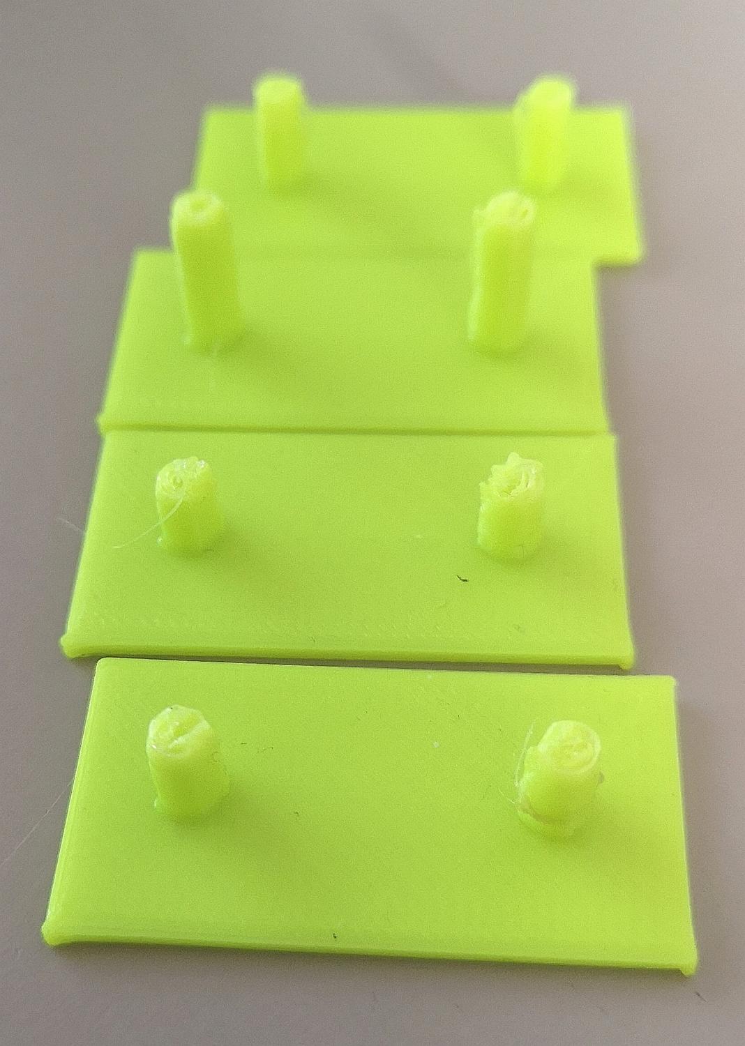
Anche grazie a queste foto sono riuscito a far funzionare la stampante. Ecco dove ho trovato un aiuto mie richieste In sostanza penso che al 90% il problema fosse la logica degli endstop, ma di grande aiuto è stata l'indicazione di ripristinare la duplicazione z tramite lo sdoppiatore del cablaggio (è un piccolo hardware senza elettronica che soppia l'uscita z). Non escludo di voler utilizzare un doppio endstop z e tornare sui miei passi visto che ora riesco a farla lavorare. Uno dei problemi più ripetitivi infatti è proprio l'inclinazione dell'asse x per piccole variazioni sulla rotazione delle viti senza fine. Comunque utilissime le tue foto.